Grid-Connected Storage Workflow: 2026 Step-by-Step Guide
- 1 day ago
- 8 min read

TL;DR:
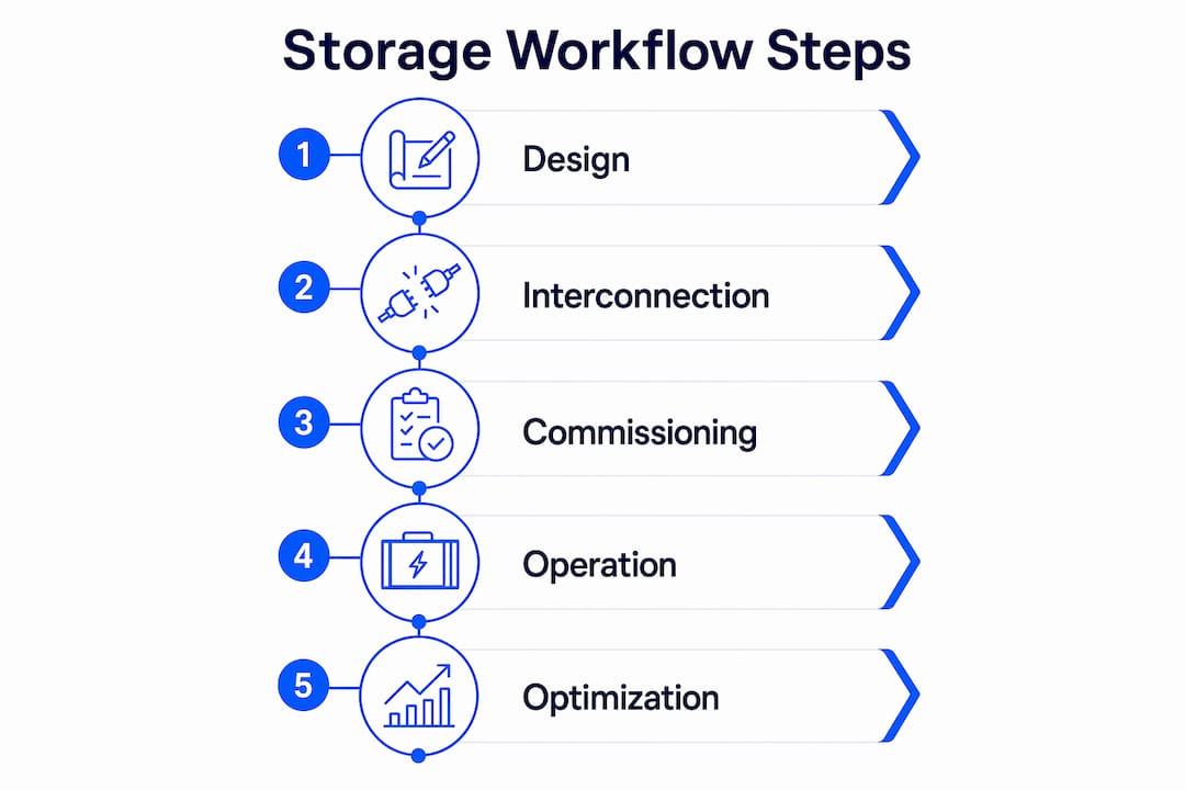
A systematic grid-connected storage workflow involves designing, interconnecting, commissioning, and operating a Battery Energy Storage System integrated with the grid for optimal energy management. Proper execution across hardware selection, software modeling, regulatory approval, and staged deployment ensures the system performs effectively and avoids costly rework. Utilizing an energy management system from the outset maximizes operational flexibility and cost savings through real-time dispatch and grid services.
A grid-connected storage workflow is the systematic sequence of steps to design, interconnect, commission, and operate a Battery Energy Storage System (BESS) integrated with the electric grid for optimized energy management. The industry standard term for this process is “grid-integrated BESS deployment,” though energy professionals increasingly use the workflow framing to capture the full project lifecycle. Executing this sequence correctly determines whether your system delivers on arbitrage, demand charge reduction, or grid services. The core components are a BESS, a Power Conversion System (PCS), an Energy Management System (EMS), and a utility interconnection agreement. Get any one of these wrong and the others cannot compensate.
What does a grid-connected storage workflow require?
A successful grid-connected storage workflow starts with hardware selection, software modeling, and regulatory groundwork completed before a single piece of equipment ships to site.
Hardware prerequisites include:
BESS modules: LFP, pre-lithiated LFP, or graphene supercapacitor cells sized to your discharge duration target
PCS or bi-directional inverter: Must support both grid-following and, for new projects, grid-forming capability to provide synthetic inertia as fossil generators retire
Protection relays and metering: Revenue-grade meters, anti-islanding relays, and utility-specified disconnect switches
Site infrastructure: Concrete equipment pads, fire suppression systems, and conduit routing
Software and data inputs are equally non-negotiable. Tools like HOMER Energy and Energy Toolbase model system economics before you commit capital. Both require interval load data, typically 15-minute interval meter data covering at least 12 months, plus your full tariff structure including demand charges, time-of-use rates, and export compensation rates. Without interval data, any capacity sizing is a guess.
Regulatory prerequisites vary by jurisdiction but share a common structure. Most behind-the-meter systems under 5 MW qualify for expedited review with interconnection timelines of 60–120 days in 2026. Larger utility-scale projects face 3–9 month permit timelines, and queue positions in markets like Australia’s NEM, where battery storage now represents 49% of the interconnection queue, can add months beyond that. Some jurisdictions also require building permits for containerized storage over 20 kW connected for more than 180 days.

Pro Tip: Request your utility’s interconnection application checklist on day one of project planning. The document reveals site-specific technical requirements, such as protection relay settings and metering specifications, that directly affect your equipment procurement list.
How do you execute the workflow from design to deployment?
The full deployment sequence follows six distinct phases. Skipping or compressing any phase creates rework that costs more than the time saved.
Economic modeling and site selection. Run interval load data through HOMER Energy or Energy Toolbase to identify the optimal storage capacity and power rating. Model against your actual tariff structure, not a generic rate. Select a site with adequate transformer capacity, physical space for equipment, and grid interconnection proximity.
Interconnection application. Submit your application to the utility or ISO with a single-line diagram, equipment specifications, and a protection coordination study. FERC Order 2023 introduced a “first-ready, first-served” cluster study process to reduce queue delays. Understand your queue position and the associated upgrade cost allocation before signing the interconnection agreement.
Procurement and logistics. Battery system procurement lead times run 12–20 weeks depending on chemistry, enclosure type, and inverter selection. Coordinate delivery windows with site preparation milestones. Concrete pads, fire suppression installation, and utility meter upgrades must be complete before equipment arrives.
Site construction and pre-commissioning. Install BESS enclosures, PCS, protection relays, and communication infrastructure. Complete DC string testing, insulation resistance checks, and relay calibration before any grid connection attempt.
Energization and ramp protocol. Grid connection for systems above 0.8 kW requires a controlled ramp-up sequence with active monitoring. Hold at 25% rated power for 24 hours while logging frequency-droop response, voltage support behavior, and anti-islanding protection performance. Step to 50%, then 75%, then 100% only after each stage passes.
EMS commissioning and go-live. Configure your EMS dispatch logic, set tariff optimization parameters, and validate communication between the BESS, PCS, and utility metering. Run a 72-hour monitored operation period before declaring the system fully operational.
Phase | Key Deliverable | Typical Duration |
Economic modeling | Optimized capacity and power rating | 1–2 weeks |
Interconnection application | Signed interconnection agreement | 60–120 days (under 5 MW) |
Procurement | Equipment on site | 12–20 weeks |
Construction and pre-commissioning | Relay calibration complete | 4–8 weeks |
Energization and ramp | 100% power achieved | 3–7 days |
EMS commissioning | System fully operational | 1–2 weeks |
Pro Tip: Grid connection is the critical path in virtually every battery storage project, often outlasting battery construction time. Submit your interconnection application before finalizing equipment procurement, not after.
What are the common commissioning challenges and how do you fix them?
Commissioning failures in grid-connected storage fall into three categories: electrical interconnection errors, protection system faults, and regulatory delays.
Electrical interconnection issues typically occur at the transition points between DC battery strings, the PCS, and the low-voltage or medium-voltage grid. Common failure causes include incorrect relay settings, ground fault mismatches between the battery DC bus and the PCS AC output, and communication protocol mismatches between the BMS and EMS. The staged ramp-up protocol exists precisely to catch these faults at low power before they cause equipment damage or utility disconnection.
Protection system faults are the most technically demanding to resolve. Testing must confirm that frequency-droop response activates within the utility-specified deadband, that voltage support kicks in at the correct voltage deviation threshold, and that anti-islanding protection trips the system within the required clearing time. Any failure at these tests requires relay reconfiguration and a full retest sequence.
Grid connection remains the longest lead time and highest-risk phase in battery storage projects. Teams that treat interconnection as a parallel workstream rather than a sequential one consistently deliver projects faster and within budget.
Regulatory and queue bottlenecks are the least technically complex but the most damaging to project timelines. Interconnection queue positions can shift due to cluster study revisions, and upgrade cost allocations can change materially between the initial study and the final agreement. Build a 30-day regulatory buffer into every project schedule and maintain active communication with your utility interconnection coordinator throughout.
Verify relay settings against utility-provided protection coordination study before energization
Confirm BMS-to-EMS communication protocol compatibility during pre-commissioning, not at go-live
Document every ramp-up stage with timestamped data logs for utility compliance records
Establish a rollback procedure that returns the system to the previous ramp stage if any parameter exceeds tolerance
How do energy management systems optimize grid storage operations?
An Energy Management System, or EnMS, is the software layer that converts a commissioned BESS into a continuously optimizing asset. Without an EMS, a battery storage system operates on fixed schedules. With one, it responds to real-time price signals, load forecasts, and grid conditions.
ISO 50001-aligned EnMS deliver approximately 4% annual energy savings over a ten-year period. AI-driven EMS platforms push that figure to 25% cost reduction through dynamic optimization. The difference is the ability to process interval pricing data, weather forecasts, and demand predictions simultaneously and dispatch the BESS accordingly.
Modern EMS platforms for solar storage integration connect to over 200 hardware and software connectors, including sensors, BMS platforms, SCADA systems, and utility APIs. That hardware-agnostic architecture means you can integrate an EMS into an existing facility without replacing legacy monitoring infrastructure. Platforms like Spacewell offer cloud and API-based integration with Excel importers for rapid setup, making them accessible even for organizations without dedicated SCADA teams.
The operational benefits of a well-configured EMS include:
Battery arbitrage: Charge during low-tariff periods, discharge during peak demand windows
Demand charge management: Predict and shave peak demand to reduce monthly demand charges
Grid services dispatch: Respond to frequency regulation or voltage support signals from the ISO
Solar storage integration: Coordinate PV generation, battery state of charge, and grid export to maximize self-consumption or export revenue
EMS Capability | Without EMS | With AI-Driven EMS |
Dispatch logic | Fixed schedule | Real-time tariff and load optimization |
Grid services | Manual or none | Automated frequency and voltage response |
Reporting | Manual data export | Continuous monitoring with automated alerts |
Integration | Single system | 200+ connectors across BMS, SCADA, sensors |
Belinus integrates its centralized EMS with 15-minute dynamic tariff optimization, battery arbitrage, and grid services dispatch into a single platform. The Belinus EMS supports multi-technology storage including LFP, pre-lithiated LFP, and graphene supercapacitor systems, with a RESTful API for third-party integrations and a native mobile app for real-time monitoring.
Key takeaways
A grid-connected storage workflow succeeds when interconnection, procurement, commissioning, and EMS configuration are treated as a coordinated sequence, not independent tasks.
Point | Details |
Start interconnection first | Grid connection is the critical path. Submit your application before finalizing equipment orders. |
Size on interval data | Model storage capacity against 15-minute load and tariff data, not headline kWh metrics. |
Use staged ramp-up | Hold at 25% power for 24 hours before stepping up. This catches relay and communication faults early. |
Specify grid-forming inverters | Grid-forming capability is now a de facto standard for new projects in most markets. |
Deploy an EMS from day one | AI-driven EMS platforms deliver up to 25% cost reduction through real-time tariff and dispatch optimization. |
Why the workflow matters more than the hardware
I have reviewed enough battery storage projects to say this plainly: the hardware is rarely the reason a project underperforms. The workflow is.
The most common mistake I see is treating interconnection as a task that follows equipment selection. It does not. Grid connection consistently outlasts battery construction time on large projects. Teams that submit their interconnection application on day one of project development finish months ahead of teams that wait until the equipment is specified. That is not a minor efficiency gain. In markets with active queue management reforms like FERC Order 2023, your queue position is a financial asset. Losing it to a late application is a real cost.
The second mistake is sizing storage on capacity alone. A 1 MWh system optimized against your actual tariff structure and interval load profile will outperform a 1.5 MWh system running on a fixed charge-discharge schedule. I have seen this play out repeatedly. The economics of demand charge reduction are almost entirely determined by dispatch precision, not raw capacity.
The third point I want to make is about grid-forming inverters. Three-quarters of Australia’s large battery pipeline already specifies grid-forming capability. If you are designing a new project and your PCS vendor is not raising this in the specification conversation, ask why. Synthetic inertia requirements are moving from optional to mandatory in most developed grid markets, and retrofitting a grid-following inverter to grid-forming capability after commissioning is expensive and sometimes impossible.
Finally, validate before you scale. A pilot project with monitored results gives you the interval data and operational baseline to justify the next phase. Skipping the pilot to save time almost always produces a larger project with the same unresolved problems at greater cost.
— Marc
How Belinus supports your storage deployment
Belinus builds grid-connected storage solutions for residential, commercial, and utility-scale applications, with the EMS, PCS, and storage hardware designed to work as a single system rather than assembled from separate vendors.

The Belinus platform covers the full workflow: economic modeling through the automated 25-year financial modeling tool, hardware supply including Solis Inverters and utility-scale 400+ kWh modules, and ongoing optimization through the centralized EMS with 15-minute dynamic tariff dispatch. For commercial and industrial projects, Belinus provides custom system design from small CNI to utility scale, with a Belinus-branded PCS targeting a two-week delivery window. Explore the full range of Belinus storage solutions to find the configuration that fits your project requirements and energy management goals.
FAQ
What is a grid-connected storage workflow?
A grid-connected storage workflow is the end-to-end sequence of steps to design, interconnect, commission, and operate a BESS integrated with the electric grid. It covers economic modeling, interconnection application, procurement, construction, energization, and EMS configuration.
How long does grid storage interconnection take?
Most behind-the-meter systems under 5 MW qualify for expedited interconnection review with timelines of 60–120 days in 2026. Utility-scale projects face 3–9 month permit timelines, and active queue positions can extend this further.
What is the ramp-up protocol for grid energization?
Grid energization for systems above 0.8 kW requires a controlled ramp-up starting at 25% rated power held for 24 hours, with monitoring of frequency-droop response, voltage support, and anti-islanding protection before stepping to higher power levels.
How much can an EMS reduce energy costs?
ISO 50001-aligned EMS deliver approximately 4% annual energy savings over ten years. AI-driven platforms achieve up to 25% cost reduction through real-time tariff optimization and dynamic dispatch.
Why are grid-forming inverters important for new projects?
Grid-forming inverters provide synthetic inertia and fast disturbance response as fossil generators retire from the grid. Three-quarters of Australia’s large battery pipeline already specifies grid-forming capability, making it a de facto standard for new projects in most markets.
Recommended