Understanding Power Flows in Energy Systems: 2026 Guide
- 2 hours ago
- 8 min read

TL;DR:
Power flow describes how electrical energy moves through generation, transmission, and loads in a network. It is essential for energy management, influencing decisions from system sizing to operational safety. Modern analysis uses iterative methods like Newton-Raphson to model these flows accurately and improve grid efficiency.
Power flow is defined as the distribution of electrical energy across a network of generators, transmission lines, transformers, and loads. Understanding power flows is the foundation of every decision made in energy management, from sizing a home battery to operating a utility-scale grid. Whether you manage a commercial facility or a residential solar installation, knowing how electricity moves through your system directly determines how much you pay and how reliably your equipment runs. This guide covers the core concepts: bus types, calculation methods, power types, and practical tools that translate theory into measurable efficiency gains.

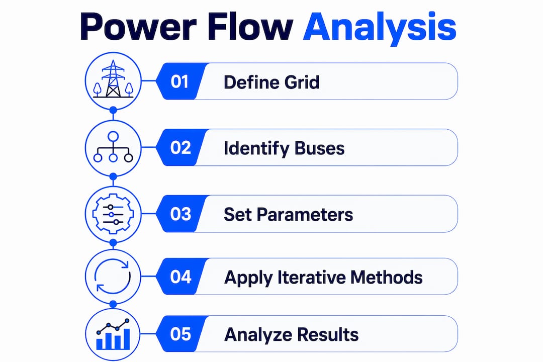
How are power flows calculated and what is load flow analysis?
Load flow analysis determines the steady-state operating conditions of a power network, including voltages, power flows, and losses at every point in the system. It is the starting point for any serious energy audit, infrastructure upgrade, or grid connection study. Without it, engineers and energy managers are guessing.
The three bus types every system uses
Every power flow model classifies each node in the network as one of three bus types. The slack bus (also called the reference bus) provides the voltage angle reference and absorbs any mismatch between generation and load, including system losses. The PQ bus has fixed active and reactive power injections, typical of load nodes. The PV bus holds active power and voltage magnitude constant, representing generators or voltage-controlled sources. The slack bus balances unknown system losses and is critical for numerical solution convergence. Miss that distinction and your model will not solve correctly.
Why iterative methods replaced closed-form solutions
Modern power systems rely on iterative numerical methods because the governing equations are nonlinear and transcendental. No algebraic formula solves them directly. For a system with n buses, the model generates 2(n−1) equations expressed in complex power form using Kirchhoff’s Current Law. The Newton-Raphson method is the industry standard for solving these equations. It uses a Jacobian matrix to linearize corrections to voltage magnitude and angle at each step, and it typically converges in 4–7 iterations for most power systems due to its quadratic convergence rate. That speed matters enormously when you are running hundreds of contingency scenarios.
Pro Tip: Never skip a load flow study when adding distributed generation to an existing network. As system complexity grows, manual calculations become unreliable fast. Formal AC load flow studies are required for compliance and operational safety in larger interconnected grids.
Load flow analysis also forms the foundational basis for specifying electrical infrastructure parameters, including rating switchboards, protective relays, and transformers. Getting these ratings wrong leads to equipment failure, not just inefficiency.
What are active, reactive, and apparent power, and why do they matter?
The three power types in any AC system are active power (P), reactive power (Q), and apparent power (S). Their relationship is expressed as S = P + jQ, where j indicates the 90-degree phase difference between the real and reactive components. Active power does the actual work: it runs motors, lights, and heating elements. Reactive power sustains the magnetic and electric fields in inductive and capacitive equipment. Apparent power is what the utility measures and bills at the meter.
Power Type | Symbol | Unit | What It Represents |
Active (real) power | P | Watts (W) / Megawatts (MW) | Actual work performed by the load |
Reactive power | Q | VAR / MVAR | Energy stored and released by inductors and capacitors |
Apparent power | S | VA / MVA | Total power drawn from the supply |
Power factor | PF | Dimensionless (0–1) | Ratio of active to apparent power |
Power factor describes how efficiently a system converts apparent power into useful work. A power factor of 1.0 means all drawn power does real work. A power factor of 0.7 means nearly a third of the current flowing through your cables produces no useful output, but it still heats conductors and stresses transformers.
Pro Tip: Businesses with large motor loads, HVAC systems, or welding equipment typically run low power factors. Installing power factor correction capacitors can cut reactive power charges on commercial electricity bills significantly, and the payback period is often under two years.
One detail that trips up even experienced engineers: in per-unit system normalization, the reactive power base equals the apparent power base numerically. Confusing these two in per-unit calculations is a common source of error that produces incorrect transformer and line ratings.
How does power flow knowledge improve real-world energy management?
Power flow analysis acts as a health checkup for electrical grids, identifying voltage deviations and overloads before they cause failures. That same principle applies at every scale, from a commercial building’s internal distribution network to a utility’s transmission system. The practical value is not theoretical. It shows up in operating costs, equipment lifespan, and energy bills.
Advanced distribution management systems that integrate data from smart meters and SCADA platforms can reduce operational costs by 12–15%, decrease distribution losses by 8.3%, and cut transformer failure rates by 34%. Those numbers come from ensemble learning models with an R² of 0.952, identifying temperature, consumption history, and time of use as the primary efficiency drivers. The implication is direct: systems that continuously analyze power flows outperform systems that react only after problems appear.
Practical steps to apply power flow insights
Audit your load profile. Map when and where your facility draws the most power. Peak demand charges often account for 30–50% of a commercial electricity bill.
Install smart metering. Real-time consumption data feeds directly into power flow models and energy management systems, replacing guesswork with measured baselines.
Monitor transformer loading. Transformers running above 80% capacity for extended periods degrade faster. Power flow data flags this before failure occurs.
Correct power factor. Identify inductive loads and add capacitor banks or active power factor correction where the ratio drops below 0.9.
Use an energy management system (EMS). Platforms like the Belinus EMS apply 15-minute dynamic tariff optimization using real-time power flow data to shift loads and dispatch battery storage at the right moment.
Run contingency scenarios. Before adding solar panels, EV chargers, or battery storage, simulate how the new load or generation changes voltage profiles and line flows across your network.
Automating energy management based on live power flow data is the step that separates facilities with flat energy costs from those still reacting to monthly bill surprises. The technology to do this is available now, not in some future grid upgrade cycle.
Pro Tip: For businesses seeking to optimize energy consumption, combining power flow analysis with automated demand response gives the fastest return. Identify your two or three largest loads, understand when they draw peak current, and schedule them around tariff windows.
What advanced power flow concepts are shaping future energy systems?
The shift toward distributed energy resources (DER) and microgrids fundamentally changes how power flow analysis works. Traditional load flow studies assume power flows in one direction: from large central generators down to loads. Rooftop solar, battery storage, and EV chargers create bidirectional flows that standard models were not built to handle without modification.
Reinforcement learning-assisted energy management frameworks in multi-microgrid networks reduce costs by 14.8% and lower loss-of-load probability from 4.8% to 2.1%. Operational feasibility improves from 84.5% to 96.1% in these systems. Those gains come from AI agents that learn optimal dispatch strategies across interconnected microgrids, something no static power flow model can replicate.
Key developments reshaping power flow analysis today include:
Unbalanced three-phase modeling. Distribution networks with single-phase solar or EV loads create phase imbalances that standard balanced models miss entirely.
Dynamic load simulation. Static load flow gives a snapshot. Dynamic simulation tracks how voltage and frequency respond to sudden load changes or generator trips.
Real-time digital twins. Utilities and large commercial operators now run live digital replicas of their networks, updating power flow solutions every few seconds using SCADA data.
Per-unit system normalization. Normalizing all quantities to a common base (typically MVA) allows engineers to compare equipment across different voltage levels without conversion errors.
Grid services integration. Battery storage systems that participate in frequency regulation or peak shaving must solve power flow equations in near real-time to respond within grid service windows.
Grid health monitoring and predictive analytics, built on continuous power flow data, are what allow battery storage systems to provide reliable grid services rather than simply storing and releasing energy on a fixed schedule.
Key Takeaways
Effective power flow analysis combines accurate bus modeling, iterative numerical methods, and real-time data to reduce costs, prevent equipment failures, and maximize energy efficiency across any system scale.
Point | Details |
Load flow analysis is foundational | It determines voltage, losses, and power at every network node before problems occur. |
Newton-Raphson converges fast | The method solves most power systems in 4–7 iterations, making it practical for large networks. |
Reactive power affects your bill | Low power factor increases apparent power draw and raises commercial electricity costs measurably. |
Smart metering enables real savings | Integrating SCADA and smart meter data can cut operational costs by 12–15% and reduce transformer failures by 34%. |
DER changes flow direction | Distributed solar and storage create bidirectional flows that require updated modeling tools and AI-assisted management. |
Why most energy managers underestimate power flow analysis
Most energy managers treat power flow analysis as something utilities do, not something their facility needs. That assumption costs money every month. I have seen commercial sites running transformers at 90% capacity with no monitoring in place, one hot summer away from a failure that shuts down operations for days. The load flow study that would have caught it costs a fraction of the downtime.
The deeper issue is that power flow knowledge changes how you think about every energy decision. Adding EV chargers without a flow study is like adding a second floor to a building without checking the foundation. The grid connection might handle it today. Under peak summer load with three chargers running simultaneously, it may not. The math is not complicated. The Newton-Raphson method, bus classification, and power factor correction are teachable concepts. What takes discipline is applying them before problems appear, not after.
The blend of theory and tools matters here. Understanding the equations gives you the judgment to interpret what your EMS is telling you. The tools give you the data to act on that judgment in real time. Neither alone is enough. Facilities that combine both consistently outperform those that rely on either experience alone or software alone.
— Marc
Belinus solutions for power flow management and energy efficiency
Belinus builds energy systems designed around the same principles this article covers: real-time power flow data, dynamic tariff response, and integrated storage that reacts to what the grid is actually doing.

The Belinus EMS applies 15-minute dynamic tariff optimization using live consumption and grid data, dispatching battery storage and managing loads based on actual power flow conditions. The Energy Wall G1, a 16 kWh graphene supercapacitor system launching in Q1 2026, pairs directly with Solis inverters and the Belinus EMS for residential and light commercial applications. For larger operations, Belinus utility storage modules scale from 400+ kWh to MW capacity with full energy management integration. If you want to move from reactive energy management to a system that acts on power flow data in real time, Belinus is the place to start.
FAQ
What is power flow analysis in simple terms?
Power flow analysis calculates how electrical energy distributes across a network, including voltage levels, line loading, and losses at every node. It is the standard method for verifying that a power system operates safely and efficiently under expected conditions.
What is the Newton-Raphson method used for in power systems?
The Newton-Raphson method solves the nonlinear power flow equations that describe a grid’s operating state. It converges in 4–7 iterations for most systems, making it the preferred tool for large-scale load flow studies.
Why does reactive power matter for businesses?
Reactive power does not perform useful work but still flows through cables and transformers, increasing apparent power demand. Utilities charge commercial customers for low power factor, so correcting it with capacitor banks directly reduces electricity costs.
What is a slack bus in a power flow model?
The slack bus is the reference node in a power flow calculation. It supplies or absorbs whatever active and reactive power is needed to balance the system, including losses, and sets the voltage angle reference for the entire network.
How does distributed solar affect power flow analysis?
Rooftop solar and battery storage create bidirectional power flows that traditional one-directional load flow models do not handle without modification. Accurate analysis of systems with distributed energy resources requires updated three-phase unbalanced models and, increasingly, AI-assisted real-time simulation.
Recommended
Comments